Ornament Spinner Unit
About a year ago there was talk of ornament spinners, and if they could be hacked for gear motors. It made sense, they were lightweight, small, cheap, and available. And now the OSU has been (mostly) perfected.
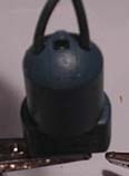
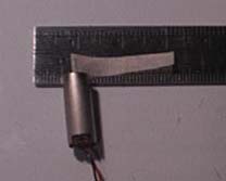
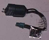 The ornament spinner is a small AC motor that is meant to plug into a string of lights. The unit is small, green, and on one end has a plastic hook that is used for hanging ornaments on. The other end has a standard light plug. I'm still looking for a simple AC driver for the unmodified ornament spinner.
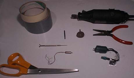 To build the OSU, you need the following:
needle nose pliers
small flathead screw driver
scissors
masking tape
duct tape
a rotary tool, or round and triangular files
pager motor (without weight)
ornament spinner
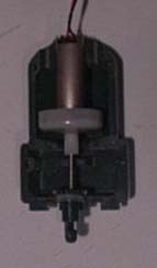
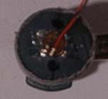
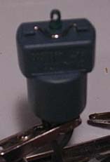 First, break into the spinner. Using the small screwdriver, pop off the spring clip that holds the end together. Its the little shiny thing in the picture. Pry at the ends of the clip, not the middle. Otherwise, it will fly! Oh yeah, try not to lose this. It is the smallest part, after all.
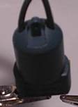
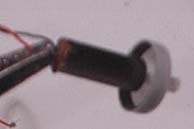
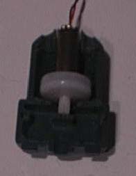
 Second, remove the interlock piece from the underside. To do this, pry the small screwdriver into the edge. Don't worry if you mar the plastic. If the screwdriver doesn't work, use the blade of a small knife. The second picture is without the interlock.
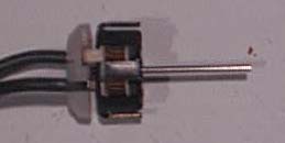
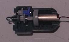
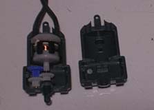 And open up the case. Don't worry if the gears are on the other side, everything is symmetrical. To continue with the tutorial, you must know the names of all the pieces. The shiny bit is the coil. It has a long non-rotating shaft that holds several of the gears in place. Below that is the magnetic rotor. The blue gear is the first gear. The blue gear and the white gear below it share a common shaft. To the right of blue gear and below the rotor is the second gear. There is a small resting point (some might consider it a bearing) between the rotor and the second gear. Below the blue gear is the third gear. The fourth gear is the green one to the right is the third gear. There is a silicon washer on the fourth gear, be careful not to lose this. The fourth gear is also the output shaft.
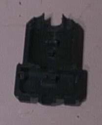
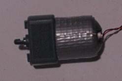
 This next step should not be rushed. The end of the motor will rest between where the wires used to go. Using a round file or rotary tool, cut a semicircle into each half. It needs it be snug and centered. Its easier to test this by placing the motor in backwards. Also, there is a nub inside that used to support the coil. This must be cut away to make room for the motor. When finished, the two halves should look something like the second picture.
 The pager motor shaft won't fit nicely onto the rotor, so a coupler is needed. Cut a piece of masking tape that is 2 cm long and not quite as wide as the pager shaft. Wrap this tape around the shaft, keeping sure that the tape doesn't drift off the shaft or into the motor. If it does, trim off the extra.
 Gently try to put the rotor over the tape. Most likely it won't fit. Unroll a bit of the tape, and cut off 5 mm. Re-roll the tape, and try the rotor again. Repeat this until the rotor fits snugly. If mistakes were made, remove all the tape and try again. This is a very important step.
 The coil's shaft is needed to hold all of the gears in place. Cut the shaft off as close to the coil as you can. Don't use pliers or wire cutters because the steel is too hard. Instead, notch it with the rotary tool's cutting disc, or a triangular file. Don't cut it all the way, its easier to break it off with pliers. You can discard the coil, or try to salvage it for a magbot.
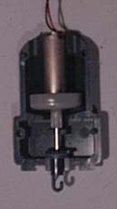
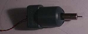
 Lay the motor in the case, and make sure that the rotor can spin freely. Next, place the smooth, uncut end of the coil's shaft into the rotor. Place the fourth gear with the silicon washer on the other end. Chances are it will be too long, and the washer will not fit inside the case (second picture). If so, cut off a millimeter at a time until the fourth gear can spin freely (third picture).
 Now that the hacking is done, all that remains is the delicate job of rebuilding. Start replacing all the gears. Everything should spin easily. Make sure that the shorter shaft that holds the first and third gears is aligned properly.
 Snap together the two halves. Replace the spring clip and duct tape the other end together. Now comes the moment of truth. Using an AA battery or two (1.5-3 volts), see if the motor turns. Don't be surprised if it makes a lot noise. If it won't work, then you have to start over. Rebuild the coupling, and make sure that everything is straight.
 If everything works, glue the motor in place. If you don't trust your craftsmanship, use hot melt glue to secure the motor.
Now you've got yourself a small gearmotor that is perfect for lightweight walkers or photovores.
<----Back
Created 12/24/01