X-cpg
Theory and Operation
So what is it? It is a compact circuit using a variable speed sequential pulse generator with its outputs connected to fixed pulse width monostable circuits. When used for motor control the circuit has a surprisingly complex set of waveforms that, among others, emulate the behaviour of microcores and bicores. Adjusting the pulse generator frequency let's you switch between those beam cores. Actually the X-cpg can be smoothly varied to simulate more complex neuron networks with less chips than other circuits of that type, microprocessors excluded. The name X-cpg stands for variable central pattern generator, although the 'X' also stands for 10, the maximum number of neurons supported. You could have more, but it's not as easy.
 In essence, the pulse generator's outputs are stretched, so the motors can continue to move. This way, more then one motor can be active when driven off of the same loop. The block diagram at right shows the basic setup. The monostable multivibrators are similar to Nv neurons. When they receive an input, they generate an output for a predetermined time. This output time is independent of the input, unlike a conventional Nv. Want more detail of monstable circuit operation? Wilf Rigter provided some simple monostable circuits which he described below.
If you're still a little confused about how the monostable multivibrators are used, maybe this hand drawn diagram may help. A bit of explanation may be needed for the depicted 'fast microcore.' At high enough speeds, the absense of a pulse allows the motor the run. This allows for a microcore gait with a much shorter time delay. In the prototype this has not been reached, due to asymetry in the pulse strechers. However, it would be easier to create the fast microcore condition in a two motor walker.
Remember where I said that a pulse generator with up to 10 neurons was the practical max? Here's why: a 4Nv microcore is good, but the PNC for higher order xNv cores rapidly becomes more cumbersome. Instead, I built the X-cpg circuit around a 4017 decade counter. It has a clock input, reset, and ten outputs that are pulsed in sequence. This makes it a perfect one chip solution. Who needs ten neurons anyways? But note: it cannot be called a core, and it doesn't have neurons. It is a very digital device.
I wanted to take full advatage of the 4017, so I built a prototype four motor walker that closely mimics Solarbotic's Scout Walker II. The X-cpg was configured for eight simulated neurons, and it was incredible. To see it smoothly go from a leisurely microcore stroll to a full out bicore gallop with the twist of a knob... Well now you can! The prototype starts out as a bicore, and transitions into microcore mode.
Download here: xcpg1.mpg 274kb
Beam Basic MonoStable circuits
Let's look at two simple monostable circuits, pictured below, these circuits can be used in place of 555 timer monostables to reduce power and component count.
 These two circuits are examples of what is variously known as the monostable, pulsestretcher or oneshot. Both circuits have an output pulse width that is independent of the input waveform. The AND gate version is slightly more compact but requires an input waveform with a fast falling edge. It requires 1 chip for 4 monostable circuits. The R1C1 product must be small compared to the R2C2 product which sets the active low output pulse width.
 The two Schmitt inverter monostable triggers from a negative slope slow changing or DC level input waveform. It must use Schmitt triggers: 74HC240s will generate multiple output transitions. With 6 inverters per IC this circuit requires 3 chips for 9 monostable circuits. Only the non-inverted output has true monostable pulses. Note that at TP3 an inverted waveform is available which is the OR of the TP1 and TP5 waveforms. This OR'd waveform may be useful in special applications.
The waveforms at key points in the circuit are shown. Note both long and short input pulses generate the same output pulse. Both circuits are non-retriggerable, i.e. the output pulse width if constant even is multiple input trigger pulses occur. The circuits will not accept a new trigger until the last pulse has timed out.
Let's look at the application of 4 monostables connected to the output of a variable frequency four output pulse generator, a microcore, driving two motors:
The monostable waveforms that drive two motors work as a continuously variable "speed control". At low frequency the circuit works like a microcore with pauses between the steps. When the frequency rises the circuit works just like a microcore. Increase the frequency more and the circuit changes to bicore type waveforms. Pushing the "speed" above the bicore gait may become a problem since the motor control pulses get shorter and the behavior changes to a rapid shuffle. Turning is accomplished by changing the monostable pulsewidths by changing the timing resistor in one or the other monostables for speeds up to and including the bicore gait. But take care, beyond the bicore gait the effect of increasing a mono pulse width for turning actually causes a reverse effect on the width of motor control pulses. Reversing will require a multiplexer (not an XOR).
For a two motor walker with "speed" control all you would need is a 4Nv voltage controlled microcore loop. That would reduce the complexity of a 2 motor walker to two 74AC14 chips or one 74HC14 and a 74AC08 chip as shown in this simple version of a two motor walker:
The Prototype
This is the version that I built:
circuit of prototype
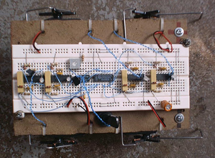
the breadboard
leg shape
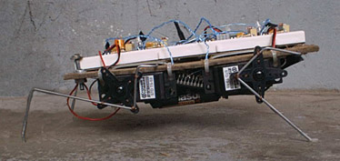
The prototype was modeled after Solarbotic's Scout Walker II. The frame was very easy and fast to build, and the motor orienation was perfect for this project. If you're planning to build a four motor walker, this is the easiest out there. Power is supplied by a tether or a 4.5 volt battery pack. The tether attachments are visible in the above view, and the battery pack can be seen in the side view. The motor drivers were tucked in the underside. One can be seen above the batteries.
Conclusion
I have thought of two possible applications for all this. The first is solar powered walkers. It can be used in ways similar to the micro/bicore of past discussion. However, the X-cpg has an infinite number of settings. Properly arranged, an LDR could influence the cpg, letting the current consumption match the solar cell. With more motors, and a much larger cell, the circuit could really shine. A four or five motor walker slowly increasing its pace would be great to watch. The second application is more for amusement. If the clock was controlled by a thermistor, lizard like responses would be generated. Pan to desert cave..... The first rays of sunlight strike him, awakening the slumber. Walking in a slow and jerky manner, it takes several minutes to achieve a confident microcore gait (maybe a little hot coffee on the thermistor would wake him faster!). As the air continues to warm, the transition begins. As the sun climbs, full leg utilization is reached. Suddenly, panic stirs in the robot. A Nu based frequency monitor informs him that he is slipping beyond bicore mode. Becoming photophobic, he runs back to the cool safety of his cave. Alas, he is too late, and the noon sun paralyzes him, until tomorrow... Pan to robobiologist with a big hat. "See, it really is alive. Even robots can suffer from heatstroke!"
Back to Circuits
Back to Home
Created 5/19/02
Revised 6/21/02