Chaos Pummer
This is a simpler verson based on Solarbotics LightStorm Pummer. Mine uses a single 74**14 instead of a pair of 74**240s. Not only that, but it also uses only two different value resistors, versus Solarbotics seven. A sigle LED is the only drawback.
Both pummers work by similar means. They run several oscillators at once. When the oscillators simultaneously output, a transistor based AND gate signals the LED driver. This driving circuitry allows the LED to slowly fade instead of a sharply flash.
On Solarbotics, four bicores with different timings make up the oscillator. The AND gate is a series of NPN transistors. This turns on the driver for a timed amount, and the driver "PUMmmmmmms" the LED.
On mine, five monocores with the same timing are used. Instead of picking odd resistor values, I took advantage of capacitor's normal varience. Where as resistors typically vary 5%, most monolithic capacitors vary 20%. This is just enough to make it random. The AND gate is the same on both. The LED driver should be adapted to the LED you're using. I happened to be using a super-bright bluish green LED from BG-Micro, part #LED1052. The circuit draws about 6ma normally, and 20ish mA when it blinks, depending on the LED. If you wanted to make it dark triggered, the LightStorm turn on circuit should work fine.
The behavior is interesting. I've watched it for some time, and it doesn't seem to repeat. When it pums, it blinks several times, followed by a long pause. Both of these are random. Sometimes is blinks once, or a few quick blinks followed short pause and more blinking. The long pause also varies. It can be short, or several minutes. At times I thought is stopped working, only to be proved wrong seconds later.
Here is the circuit: (Thanks to Wilf for pointing out a missing component!)
While the circuit itself is rather compact, my breadboard thinks otherwise:
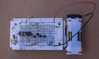
Maybe I should clip component leads....
New:
Even though I tried to make this pummer as simple as possible, Wilf Rigter made it a little smaller. 14% smaller, to be exact, by reducing the pin count from 71 to 61.
The improvement is in the AND gate. The original was a duplicate of the LightStorm's gate, with an extra input added, for a total of five transistors and five resistors. Wilf replaced this transistor logic with diode logic, instead using one transistor, one resistor, and six diodes. The sixth, tied to ground, is used is raise the switching threshold of the transistors.
And here is is:
Back to Circuits
Back to Home
Created 6/7/02
Updated 8/17/02