Alt-BEAM Archive

Message #09179


To: "beam mailing list" beam@sgiblab.sgi.com
From: "David Perry" davidperry@geocities.com
Date: Fri, 14 Jan 2000 17:05:57 +1100
Subject: [alt-beam] pricing and design specs for modular nv


content-transfer-encoding: quoted-printable

Okay after working all day (in this bloody 35 degree heat wave) i have come=
up with some estimated pricing and designs.

First the pricing, this includes
PCB
SMD LED
SMD resistor
SMD pot (2 meg)
.22uf monolithic cap
nc7s14 fairchild tiny logic single gate scmitt inverter =

4 pin in connector
4 pin out connector
2 pin header
3 pin header
two 1 pin header
two jumpers.

The total cost comes to about $4.50 which is more than i expected, but i ca=
n get it lower using slightly different parts.

It runs as a normal NV neuron but there are a few things, jumper A is desig=
ned to give bias, you can adjust the pot to the value you want (0 ohms if y=
ou want) then you use the two pins to add whatever bias you want, also hand=
y cause you can just plug it in using a connector. When you aren't using th=
e bias, set the pot to the value you want and use the jumper to join the re=
sistor to ground. =


Jumper B has three headers. The first is to connect your output to (motor =
driver). The next two allow you to turn on or off the LED.

The 'board in' Connector (male) is located on the side of the board, it pro=
vides power from the previous neuron. It also gives the output from the pre=
vious neuron to the input of the current one. The spare connector (which ha=
s a jumper) can be used for any cross board application, it's just an auxil=
lary to add more functionality, use your imagination on just how to use it =
(bias, sensors, data bus).

The 'board out' connector (female) is pretty self explanatory. It has two p=
ower connectors to pass power to the next neuron. Also has the output from =
the current neuron to give to the input of the next. The spare connector is=
the same as above.

Boards can either be connected directly side to side or with a cable. Power=
only has to be provided to one neuron, which could be done by soldering wi=
res onto the power pads, or i could add connector (but theres enough alread=
y).

The whole thing would be surface mounted to a small PCB, in the shape of a =
triangle of hexagon. That means that eventually cables will be required or =
connectors used on multiple sides of the PCB. You could also have blank con=
nector boards but that just adds to cost and complexity.

What do you think?

David


content-transfer-encoding: quoted-printable


two jumpers.


The total cost comes to about $4.50 which is more than =
i =

expected, but i can get it lower using slightly different parts.
V>
 

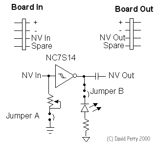
It runs as a normal NV neuron but there are a few thing=
s, =

jumper A is designed to give bias, you can adjust the pot to the value you =
want =

(0 ohms if you want) then you use the two pins to add whatever bias you wan=
t, =

also handy cause you can just plug it in using a connector. When you aren't=
=

using the bias, set the pot to the value you want and use the jumper to joi=
n the =

resistor to ground. 


 Jumper B has three headers. The first is to conne=
ct your =

output to (motor driver). The next two allow you to turn on or off the =

LED.


The 'board in' Connector (male) is located on the side =
of the =

board, it provides power from the previous neuron. It also gives the output=
from =

the previous neuron to the input of the current one. The spare connector (w=
hich =

has a jumper) can be used for any cross board application, it's just an =

auxillary to add more functionality, use your imagination on just how to us=
e it =

(bias, sensors, data bus).


The 'board out' connector (female) is pretty self expla=
natory. =

It has two power connectors to pass power to the next neuron. Also has the =

output from the current neuron to give to the input of the next. The spare =

connector is the same as above.


Boards can either be connected directly side to side or=
with a =

cable. Power only has to be provided to one neuron, which could be done by =

soldering wires onto the power pads, or i could add connector (but theres e=
nough =

already).


The whole thing would be surface mounted to a small PCB=
, in =

the shape of a triangle of hexagon. That means that eventually cables will =
be =

required or connectors used on multiple sides of the PCB. You could also ha=
ve =

blank connector boards but that just adds to cost and complexity.
IV>
 

What do you think?


David


Attachment: nvmodule.gif

Home